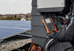
Polarity, Voc, Isc, operating current and insulation resistance: expected PV string values and how to measure them...









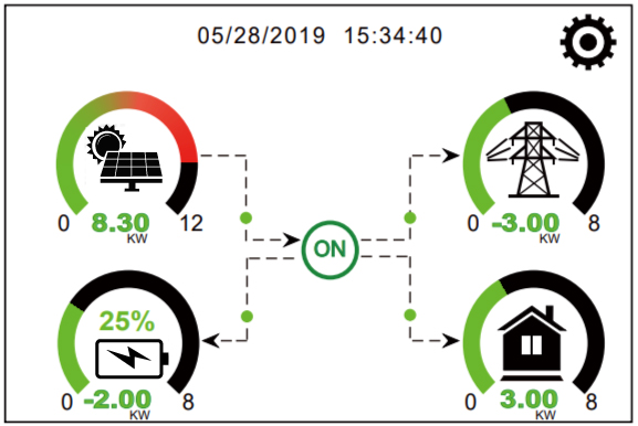
Understanding the main screen
Where does electricity come from and where does it go?
The Deye chooses at any time between the panels, the battery and the grid to power the house.
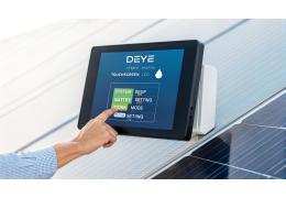
The main screen shows four elements connected by arrows. Before changing a setting, look at which arrows are active. If the grid receives energy while the house is consuming power, the cause is often a measurement or wiring problem — not a hidden menu.
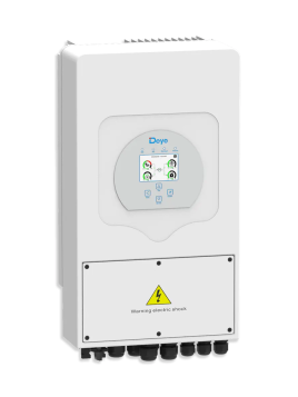
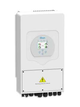
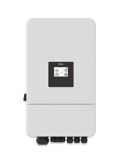
This explanation mainly applies to the SUN-3K to SUN-8K-SG04LP1-EU single-phase residential models and their three-phase equivalents. Unlike a conventional solar inverter, a Deye can charge and discharge a battery, create a backup supply and manage energy in several directions.
At a glance
The Deye chooses the path of electricity
Follow the line that corresponds to the current situation.
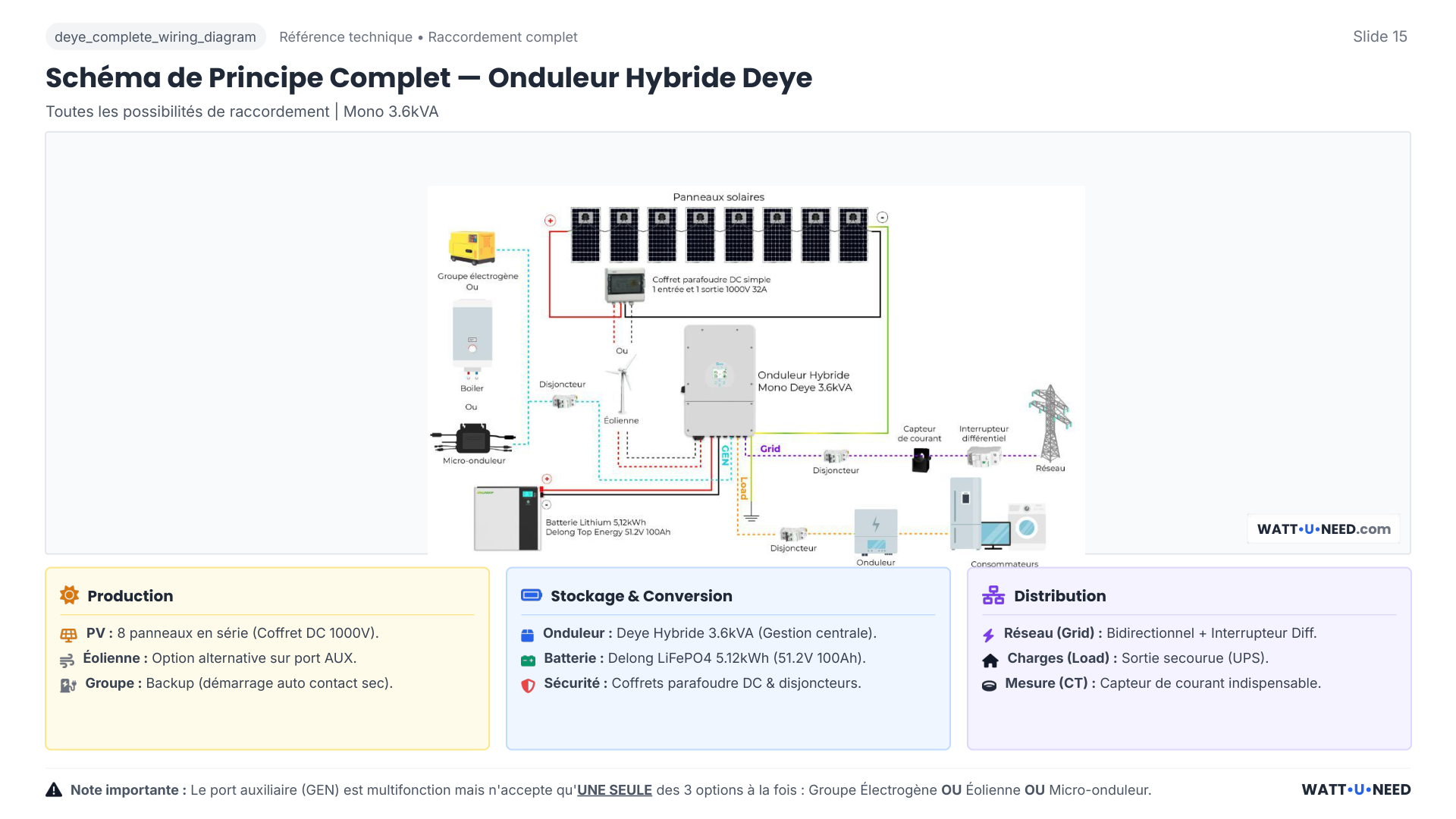
PanelsThey produce
Deye inverterDistributes energy
HomeUses energy
BatteryIt charges or discharges
Deye
GridSupplies or receives energy
Technical values to rememberMPPT, battery voltage and energy circulation
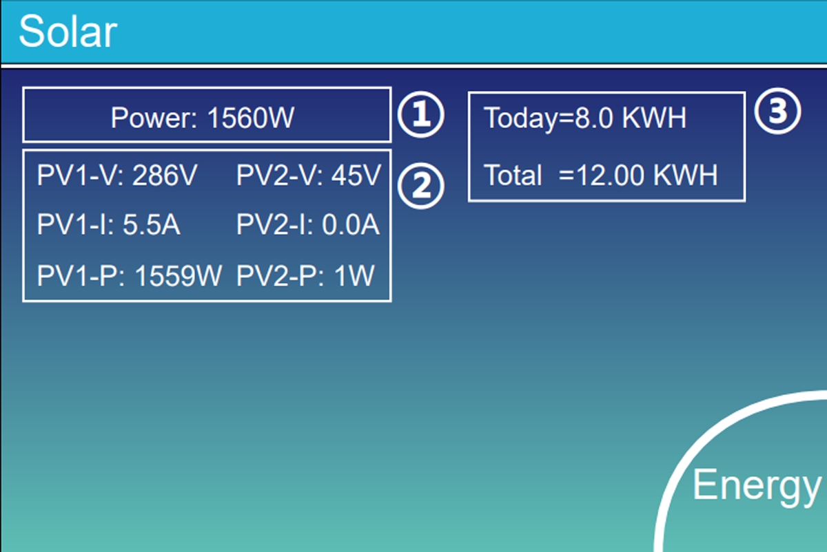
Solar production
The panels power the house and recharge the battery. On the models covered by this guide, the MPPT range is generally 150 to 425 V. A string outside the model’s operating range will perform poorly, even with correct settings.
The energy reserve
The low voltage battery bus generally operates between 40 and 60 V. An internal bidirectional converter called Buck-Boost can circulate energy in both directions between panels and battery; its limits depend on the currents set.
Grid support
The grid provides what is missing. If the contract authorizes it, he can also receive the solar surplus.
Grid connection
The inverter here takes what is missing or returns the authorized surplus.
Backup circuits
Priority devices remain powered during an outage. The changeover is generally accomplished in less than 10ms ; Backup Delay can modify this behavior depending on the model.
Multifunction port
Generator, Smart Load or AC coupling: one function at a time.
House measurement
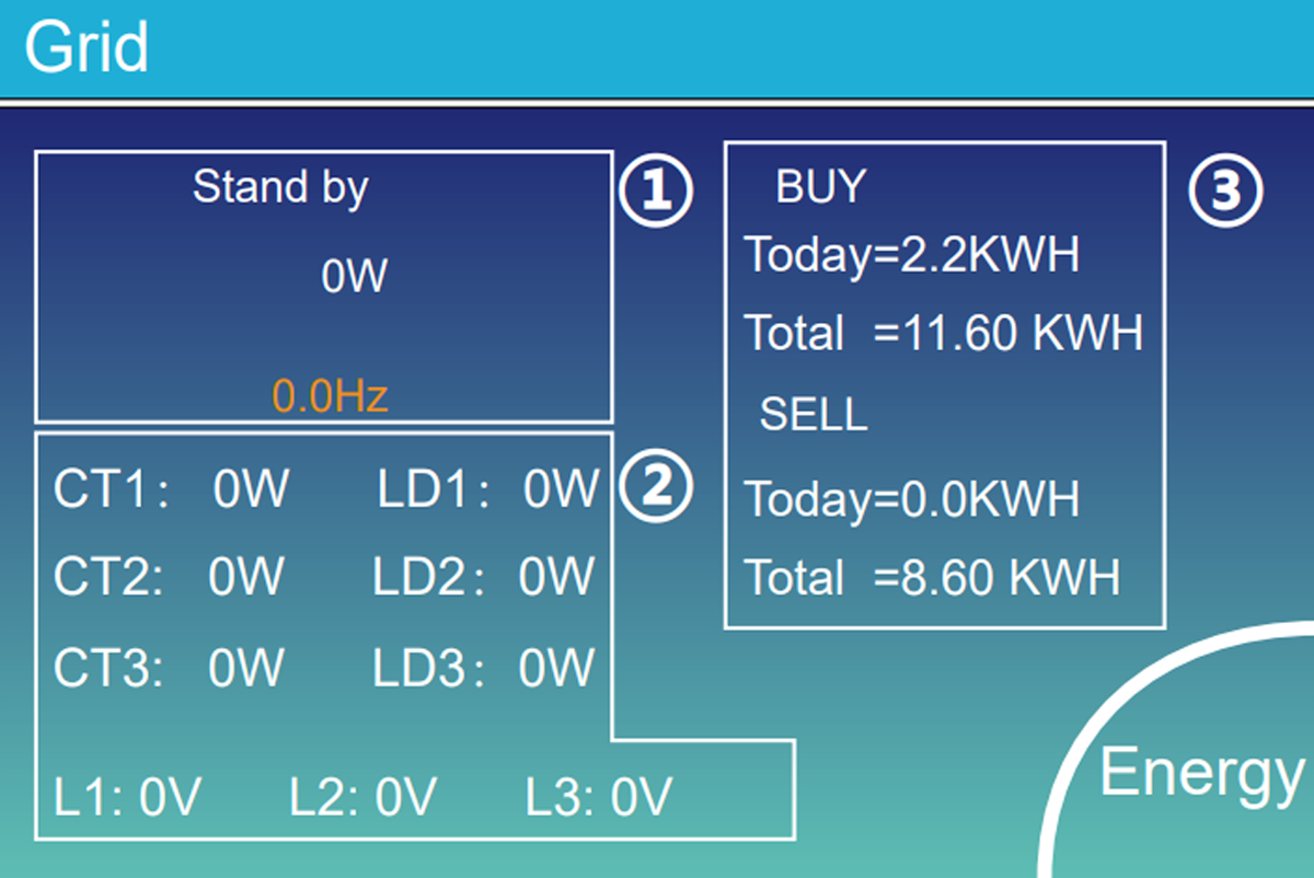
The clamp tells the Deye whether the house is taking or returning electricity.
If the arrows are not going in the right direction
Don't change five settings at random. Switch the sources off one by one and see what changes on the screen. This way you will know if the problem comes from the panels, the battery or the grid measurement.
The 150–425 V and 40–60 V values are guidelines, not a universal authorization
The exact reference and its manual remain priority. High voltage versions or newer series may use other ranges.
Prepare for commissioning
Checks to do before opening the menus
Write down these six pieces of information before you begin. They will prevent you from choosing a setting that does not suit your installation.
- 1Exact reference
SG series, power, single phase or three phase, low or high voltage and manual version.
- 2Solar panels
Note how many panels are connected to each PV input. Also check the +, the − and the maximum possible voltage when it is very cold.
- 3Batteries
Note the model, number of batteries, their capacity and the maximum current allowed for charging and discharging.
- 4Battery communication cable
Check the socket used on the battery and on the Deye, then select the battery type intended by the manufacturer.
- 5CT clamp or counter
Check where the measurement is installed, the direction of the arrow and, in three-phase, that each clamp corresponds to the correct phase.
- 6Energy objective
Zero injection, sale, backup, hourly rate, Smart Load, generator or AC coupling.
Maximum battery current
The most limited hardware sets the maximum value
Simple example
min (inverter · BMS · modules · cables · fuses)
Example: 120 A inverter, 100 A cable, a Pylontech US3000C 37 A. The battery being the most limited, the setting cannot exceed 37 A.
The charging current and discharge current may be different. Do not copy not the value of another installation: check the limits indicated on the battery, the cable, the fuse and the instructions for your Deye.
| Example from the original guide | What to remember |
|---|---|
| Battery of a Deye 6 kW: up to 135 A | If the cables only support 100A, never leave 135A in Max Charge or Max Discharge Current. |
| 25 mm² battery cable: approximately 100 A over short distance | The length, installation, temperature and protections may impose less. Have the actual calculation validated. |
| GRID and LOAD, 3.6 to 6 kW models: example 6 mm² / AWG 8 and 40 A circuit breaker | These are values taken from the models targeted by the article; the manual, the RGIE or NF C 15-100 and the site plan remain priority. |
| 32 A upstream circuit breaker | Do not set the inverter to import 40A to charge the battery and power the house: the circuit breaker will eventually trip. |
CT and counter
How to simply check the direction of the CT clamp
- 1
Isolate the panels and battery with the provided disconnectors, so that the inverter can only use the grid. Never unplug a PV connector under load.
- 2
Turn on an easy-to-recognize device, for example a kettle or heater of 1 to 2 kW.
- 3
Look at the main screen. The arrow should start from the pylon on the left, go towards the inverter, then towards the house at the bottom right.
- 4
The Grid value should increase. If the arrow goes the other way or stays near zero, stop the test and have the direction or location of the CT clamp checked.
An adjustment never replaces a circuit breaker or fuse
The circuit breakers, fuses, sections, clamping, differentials and neutral regimes remain to be designed and controlled depending on the country, the grid and the equipment installed.
System Setup and Basic Setting
Set the correct time and unlock the settings
Start here to avoid a program starting at the wrong time or a menu getting stuck.
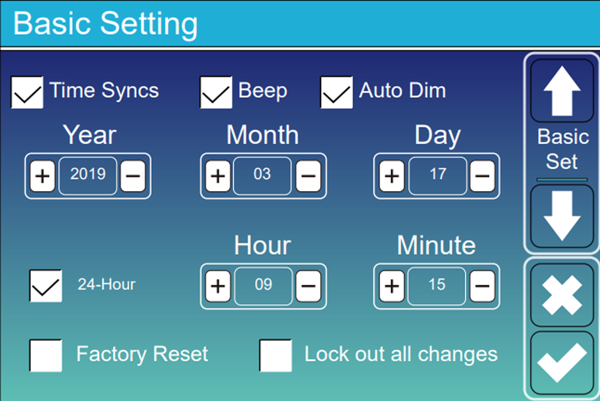
Time, date and Time Sync
The inverter uses its clock to start each time slot at the right time. Just check that the time and date displayed are correct.
On some devices, the internal clock RTC can drift by several minutes per day. With the Wi-Fi dongle, Time Sync resynchronizes the time using the time server NTP from Deye or Solarman. Without this, a planned off-peak charge may end up starting during peak hours.
A correct time also makes error logs usable: you will be able to link an alarm to what actually happened in the house.
Unlocking changes
In Basic Setting, disable Lock out all changes and use 7777 when the screen asks for the installer code.
9999 corresponds to the factory reset: do not use it to simply modify a parameter.
| Setting | Role | Recommended inspection |
|---|---|---|
| Code 1234 | User access and initiation of certain procedures such as System Self-Check. | Use it only for the functions provided by the manual and the grid standard. |
| Code 7777 | Installer access to critical settings when Lock out all changes is disabled. | Photograph the values before any modification. |
| Code 9999 | Factory Reset: erases the entire configuration. | To be reserved for a voluntary and prepared reset. |
| Time Sync | Automatically resets the clock to the correct time. | Compare screen time with your phone. |
| Lock out all changes | Prevents unintentional changes. | Disable to adjust, then secure access. |
| Beep | Allows the audible alarm, including the shrill beep of Low Batt. | Leave it active to be notified of a fault; turn it off only if the device is in a living room. |
| Auto Sun | Automatically reduces screen brightness. | Enable it to save the backlight without hiding the alarms. |
One change at a time
Take a photo of the screen before editing, note the original value and verify that Save or OK actually saved the change.
Safety before performance
Adjust the battery correctly without damaging it
Enable BMS communication, properly limit power, and choose what should happen when the battery gets low.
Lithium mode with communication
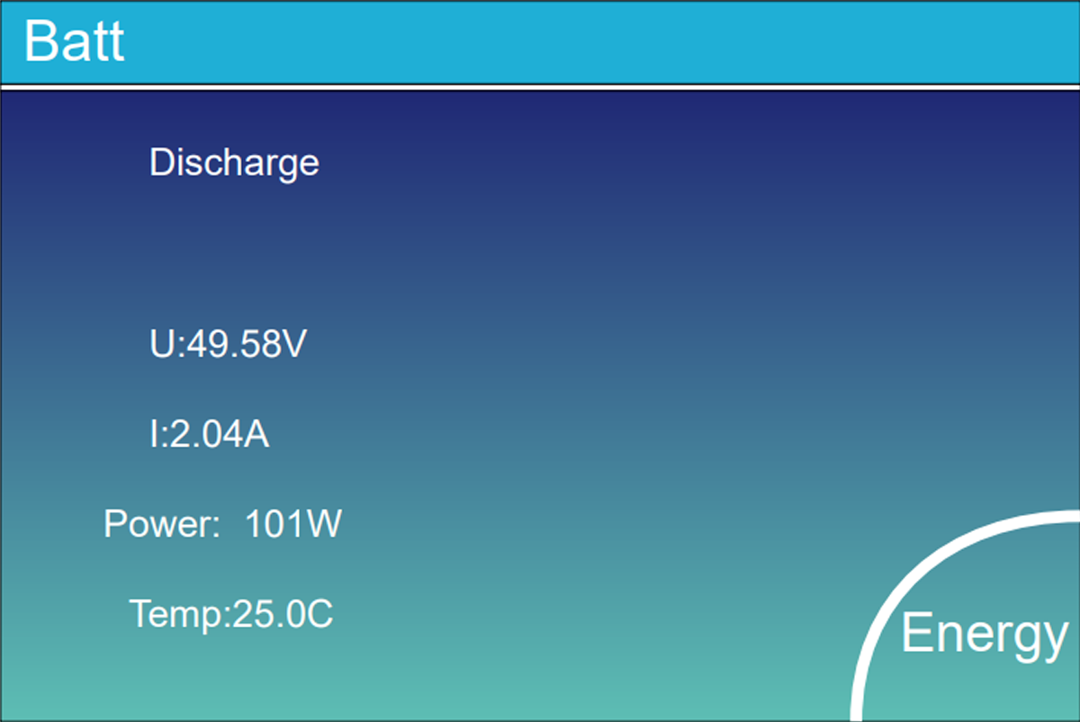
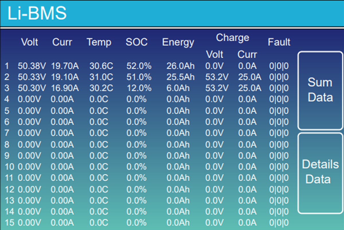
Best used with a compatible battery. The battery directly indicates to the Deye its percentage, its temperature and the current it can accept.
- Select the Lithium type.
- Select the code provided for the battery brand and model. The codes 00 Or 12 exist on some associations, but should never be chosen without checking the compatibility table.
- Use the intended CAN or RS485 connection. The BMS can then automatically reduce the current if the battery is cold, too hot or almost full.
- When the BMS communicates, its instructions become priority; the Float and Absorption manual tensions can then be secondary or grayed out.
- Check that the percentage and temperature appear on the screen.
- Enable BMS_Err_Stop once the communication has been validated.
Voltage or percentage mode
Reserve for lead or batteries that cannot communicate with the Deye. The inverter then tries to estimate the battery level using voltage alone.
With a LiFePO4 battery, the voltage moves very little between around 20 and 80%. Under a load of 100 A, it can also drop for a few seconds: the Deye can read 46 V and cut off while the battery still displays 40%. This is the Voltage Sag, in other words a momentary drop in voltage under high consumption.
Two options to understand
Activate Battery and BMS_Err_Stop do not pursue the same objective
Activate Battery
This function is used to try to wake up some completely shut down batteries. Leave it disabled for normal use and follow the manufacturer's procedure if the battery no longer starts.
BMS_Err_Stop
Activate this option with a communicating lithium battery. If the BMS cable is unplugged or defective, the Deye will shut down instead of continuing without knowing the actual battery status.
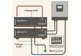
Pylontech US2000 / US3000 / US5000: do not exceed the planned ceiling
Special case PylontechDeye + Pylontech: boot order, wiring, protocol and voltage ceilingsConsult the dedicated procedure before commissioning →These 15S batteries must remain at 53.5V maximum, with 53.2 V recommended in the original article. A 16S pack, often rated around 57–58 V, does not use the same cap. With Pylontech, keep Activate Battery OFF in normal operation and let the BMS control charging.
Max A Charge / Max A Discharge
Three limits to compare before entering a current
| Element | Example | Consequence |
|---|---|---|
| Inverter | 120 A on a 5 kW model | This is its limit, not necessarily the one that the entire installation accepts. |
| Cables | Around 100 A for 25 mm² over short distance | Never exceed the capacity actually calculated for cables and protections. |
| Battery | 37 A for a US3000C; 74 A for two identical modules in parallel | The number of modules and the manufacturer’s datasheet determine the available current. |
To promote longevity, the original guide recommends staying around 0.5C continuously: for example 50 A for a 100 Ah battery, even if it briefly allows more. Too high, the BMS may cut off for overcurrent; too low, the installation will absorb a large solar surplus less well.
End of autonomy
Three thresholds, plus the minimum Time of Use: four levels not to be confused
WATTUNEED · DEYE GUIDE 2026
Shutdown, Low Batt, minimum Time of Use and Restart
Four levels, four different roles. Always keep them in this order.
Shutdown
What does it do?
Cuts the AC output when the battery reaches its lower limit, especially when the grid is unavailable.
Do not confuse it with
The chosen value must remain compatible with the BMS and the battery.
Quick example5%
Low Batt
What does it do?
Triggers the low-battery alarm and the piercing beep when Beep is enabled.
Do not confuse it with
This level does not replace the daily minimum set in Time of Use.
Quick example10%
Minimum Time of Use
What does it do?
Sets the minimum battery level kept during the daily operating schedule.
Do not confuse it with
This is neither Shutdown nor the Low Batt alarm.
Quick example15%
Restart
What does it do?
Allows the AC output to resume after the battery has recharged sufficiently.
Do not confuse it with
Setting it too close to Shutdown can cause repeated start-stop cycles.
Quick example30%
Complete scale
5%Shutdown10%Low Batt15%Minimum Time of Use30%Restart
Keep the order: 5% < 10% < 15% < 30%.
See the full explanation of the four levelsWhat they do, what they don’t do, and why you should keep a gap.
| Level | What it causes | What should not be inferred |
|---|---|---|
| Shutdown | Cuts the AC output when the battery reaches its low limit, especially off-grid. The quick example uses 5%. The original article also gave 10–15% as a common starting range. | This setting does not replace the BMS protections. It must remain compatible with the battery. |
| Low Batt | Triggers the low battery alarm and the shrill beep if Beep is active. Depending on the mode and firmware, it can also participate in reserve management when the grid is present. Quick example: 10%. | It mainly serves as a warning. This is not the minimum used each day. |
| Minimum Time of Use | When the grid is present, the battery can work up to the minimum indicated in the time slot. With 15%, the grid then takes over according to the chosen setting. | This is neither a Shutdown outage nor the Low Batt alarm. |
| Restart | Authorizes AC recovery after sufficient recharge. The quick example uses 30%; a range of 30–40% is also commonly used. | Setting it too close to Shutdown can cause on/off cycling. |
Maintain order Shutdown < Low Batt < minimum Time of Use < Restart. The four values can be moved closer together or lowered, but they must always remain compatible with the battery manufacturer’s and BMS requirements.
Keep sufficient margin before Restart. 15 to 20 points difference is a good starting example, to be adapted to the battery and use. Otherwise, at sunrise, the inverter can reboot, turn on a refrigerator again, immediately fall back to Shutdown and start again non-stop.
Batt Set 2
Grid Charge and Gen Charge: who has the right to fill the battery?
Grid Charge
Leave this option disabled if you want to maximize solar self-consumption. Activate it in TOU ranges if you want to buy off-peak to use the energy later.
Gen Charge
This option allows the generator to charge the battery. Adjust the current so that charging and home consumption stay together around 70 to 80% of the nominal power of the generator, in order to prevent it from stalling.
Does the voltage drop when a large appliance starts?
Do not lower Shutdown directly. First check if the current is too high, if the cables are getting hot, if a terminal is loose or if the battery is cold.
Define the energy strategy
Choosing when to use solar, battery or grid
In System Work Mode you simply decide where the electricity comes from, at what times and how much battery you want to keep.
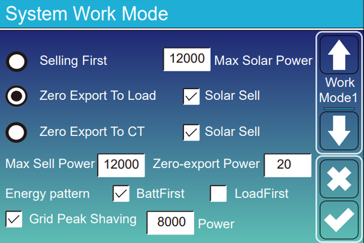
| Fashion | Perimeter observed | Use | Point of vigilance |
|---|---|---|---|
| Zero Export to CT | The whole house, thanks to the CT pliers. | Use solar without sending electricity back to the grid. | The CT clamp must be in the right place and in the right direction. |
| Zero Export to Load | Only devices connected to LOAD. | Fallback solution when no CT clamp is installed. | Other appliances in the house, such as a water heater left on the main panel, are not taken into account. |
| Selling First | Home, then battery, then grid. | Sell or inject the surplus when the contract allows it. | Limit the power with Max Sell Power: for example 3 kW if the contract limits injection to 3 kW, even with a 5 kW inverter. |
| Solar Sell | Surplus after internal priorities. | Allow residual injection. | Check only if injection is permitted. |
Solar Sell and Zero-export Power complete the chosen mode
Solar Sell authorizes the sending of the surplus to the grid. In zero injection mode, we generally keep very low consumption from the grid to prevent the Deye from sending a few watts by mistake. Set this margin only after checking the CT clamp.
Energy Pattern
Load First or Batt First: what do you recharge first?
Load First
Solar first powers the devices in the home, then recharges the battery with what’s left. This is generally the best efficiency, because a charge/discharge cycle only restores around 85 to 90% of the energy.
Batt First
Solar recharges the battery first. This choice is useful if you want to quickly find a reserve in the event of a power outage.
Max Sell Power
Limits export to the power authorized by the contract and connection.
Time programming
Time of Use: telling the battery when it can work
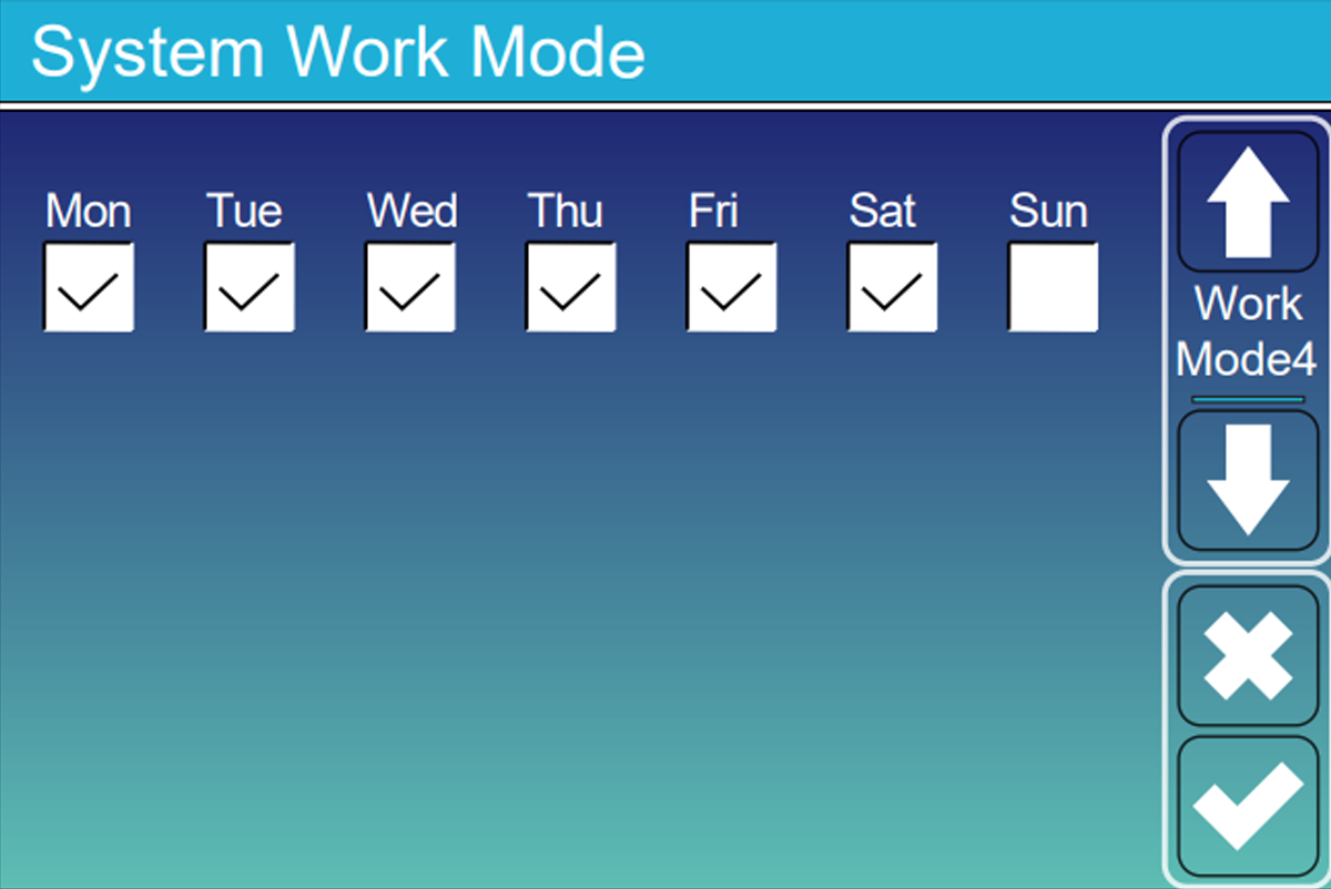
Check first Time of Use. The Deye divides the day into six periods. Each period has a start time, a power limit, a minimum battery percentage and permissions for grid or generator charging. Remember to tick the days on which the programme must run.
From what time?
Each line begins at the specified time and ends when the next line begins.
At what power?
Contrary to common confusion, this value is generally the battery discharge power limit for that period, not its charging power.
How much to keep?
With Batt = 15%, the Deye can use the battery up to 15%, then it goes to the grid.
Can we recharge?
Check Grid Charge to allow charging from the grid, for example during off-peak hours.
| Setting | What the Deye includes |
|---|---|
| 10 a.m.–2 p.m. Batt 100% | Keep the battery full. Solar can charge it, but it won't discharge to help the house as long as the set point remains at 100%. |
| 6 p.m.–10 p.m. Batt 40% | Allow the battery to power the house up to 40%, then take over from the grid. |
| 02:00–06:00 · Batt 80% · Grid Charge ON | Allow the grid to charge the battery up to 80%, for example during off-peak hours. |
| Scenario | Floor Batt | Grid Charge | Expected behavior |
|---|---|---|---|
| Night at reduced rate | Percentage to reach | Yes | The grid can recharge the battery up to the requested percentage. |
| Solar day | Reserve desired | No | The panels recharge the battery; the grid does not recharge it. |
| Evening | Minimum to keep | No | The battery powers the house up to this minimum. |
Work Mode 4: unchecked days do not execute the TOU table
In Solarman, days can appear on a page named System Work Mode 1 while the manual talks about Work Mode 4. If Sunday is unchecked, Deye reverts that day to its general strategy — for example Zero Export to CT + Load First — with only Low Batt as overall protection.
In front of the inverter screen
Quick setup in four screens — not a miniature manual
The minimum journey to unlock settings, secure the BMS, set thresholds and enable scheduled discharge.
4
essential screens
5
minutes, approximately
1
final check
Screen 01
Basic Setting
Unlock changes
- To do
- If “Lock out all changes” is active, deactivate it and validate with code 7777.
- To be checked
- The configuration fields become editable again.
- Attention
- Do not use 9999: this code corresponds to resetting the parameters.
Screen 02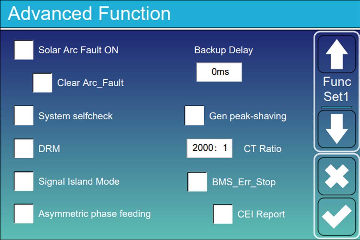
Advanced Function
Secure communication BMS
- To do
- With a communicating battery in CAN or RS485, activate BMS_Err_Stop.
- To be checked
- In the event of loss of BMS communication, the inverter stops and reports the fault.
- Attention
- Check that the cable is plugged into the correct sockets and that the correct battery type is selected: a BMS loss can cut off the backup.
Screen 03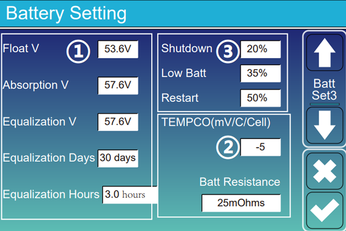
Battery Setting · Set 3
Define the three battery thresholds
- To do
- Advanced example: Shutdown 5%, Low Batt 10%, Restart 30%. Adapt these values to the battery and its BMS.
- To be checked
- The order remains consistent: Shutdown < Low Batt < Restart.
- Attention
- Shutdown stops the DC/AC module in off-grid mode; it does not physically disconnect the battery.
Screen 04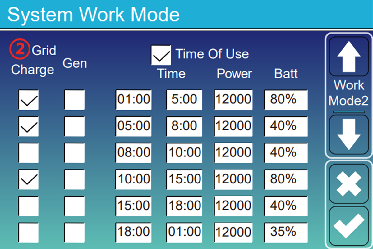
System Work Mode · TOU
Allow the battery to work
- To do
- Check Time of Use then indicate, for example, Batt = 15% to allow discharge up to 15%.
- To be checked
- With the grid present, the battery powers the loads according to the selected ranges.
- Attention
- “15%” is the minimum to keep in the battery, not a discharge limited to 15 points.
Reading example
The four-level staircase
Deliberately low example: check these values against the battery datasheet and BMS.
5 %ShutdownOff-grid DC/AC shutdown
10 %Low BattAlarm ; beep if activated
15 %Minimum TOUThe grid takes over
30 %RestartAC recovery after recharging
Shutdown < Low Batt < minimum Time of Use < Restart
These values are not a universal preset
They can be raised or brought together when the manufacturer and BMS allow it. Too little margin can trigger alarms or repeated shutdown and restart cycles.
LCD referenceFind the 14 commented Deye screens
One entrance, three uses
Choose what port GEN is used for
It can be used for the generator, the Smart Load or another solar inverter. Choose a single function and check that the connection matches.
PORT GEN
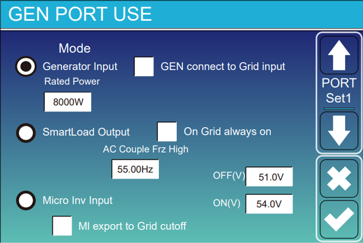
Smart Load: predict ON and OFF
The activation threshold must be greater than the deactivation threshold. Example from the guide: activate at 95 % of battery and only if there is at least 500 W solar. Add a margin to prevent the load from switching with each cloudy period.
On Grid Always On keeps the output powered when the grid is present. The intelligent thresholds then become especially useful during an outage.
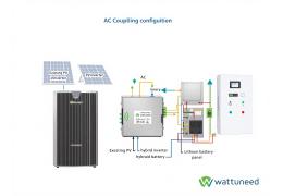
AC coupling: check compatibility
When the grid cuts out and the battery is full, the Deye gradually increases the frequency of the grid it creates: 50, 51, then possibly 52 Hz. The other inverter must understand this signal and reduce its production.
AC Torque Fre High sets the stopping frequency. Too low, the microinverters cut out for no reason; too high, they risk continuing to produce while the battery can no longer absorb the energy. Do not copy the value of another brand.
Mutually exclusive functions
The port cannot simultaneously be a generator input and a Smart Load output. Any external switching must be designed as a dedicated electrical installation.
Grid Setting and Advanced Function
grid and security settings
These menus are not used to improve production. They must correspond to the country, the connection and the electrical diagram of the house.

Choose the correct country or grid code
This choice regulates the voltages, frequencies and disconnection times. Do not use General Standard if the manager requires, for example, VDE 0126 Or EN 50549. In Italy, CEI 0-21 can request a System Self-Check launched with code 1234.
Keep differentials effective in the event of a cut
When the grid disappears, the neutral of LOAD can become floating. Signal Island Mode can control a contactor which temporarily connects neutral and earth on the emergency side to recreate a TN-S regime. Wiring depends on the model and must be designed by an electrician.
Detect poor contact on the panel side
Poor MC4 contact can create an arc. If the model has Solar Arc Fault ON, the inverter analyzes the DC current and cuts off the MPPT if it recognizes an arc. This safety does not replace good connectors and tightening.
Avoid exceeding the meter power
You can set, for example, an import limit of 6 000 W. If the house requires more, the battery supplies the difference. Keep enough energy in the battery for these peaks.
Field procedure · Single- and three-phase Deye SG05
Neutral-to-earth bonding: what is shared, and what changes
The principle is the same across the SG05 family: in backup mode, the LOAD output needs the correct neutral-to-earth bond; when the grid returns, that bond must be removed. The switching hardware is not identical on every chassis.
On versions with two Parallel DIP switches and two ATS DIP switches, set all four switches upwards to ON.
PARALLELONON
ATSONON
The manual describes Signal Island Mode, but not the four ATS DIP switches. Follow the wiring diagram for the exact model; do not copy the single-phase DIP layout.
Advanced Function✓ ATS / Signal Island Mode enabled
Related parameter, when presentOFF ATS Mode
GRID AVAILABLE
Normal startup
- 1
Switch on the grid.
- 2
Start the battery.
- 3
Press the inverter ON/OFF button.
- 4
Wait until the inverter has completed startup.
- 5
Then switch on the PV panels.
Expected resultThe inverter starts normally, without an anomaly.
GRID UNAVAILABLE
Battery-only startup
- 1
Start the battery.
- 2
Press ON/OFF.
- 3
Do not touch anything for 2 to 10 minutes. Wait until the inverter is actually supplying the LOAD output.
- 4
Once LOAD is powered, switch on the PV, then the grid when it returns.
What you may seeThe inverter enters bypass, but still shows Off-grid and the switching does not reactivate correctly.
1
→Press ON/OFF
2
→Wait until the display shows OFF
3
→Press ON/OFF again
✓
Normal operation and switching are restored
Before moving DIP switches: isolate and secure all sources as required by the manual. This procedure applies only to SG05 units whose terminals and menus match the labels above. With more than six inverters in parallel, the Parallel DIP positions change: follow the manual. The N–PE bond, relay and protective devices must be checked by a qualified electrician.
A neutral-earth error can cause a short circuit on the grid return
Signal Island Mode is more than just checking a box. The contactor, its type, its wiring and the neutral regime must correspond to the exact installation diagram.
Do not touch the F(W), V(W) or V(Q) curves without specific instructions
These settings are imposed by the grid operator. A wrong choice can prevent the inverter from connecting or make the installation non-compliant.
Do not leave the site too early
Perform four tests before leaving the installation
A saved setting is not enough. Check on the screen that the house, battery and grid are responding as expected.
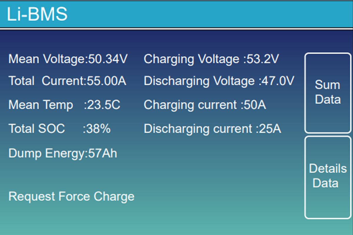
- 01Watch the screen without heavy consumption
The battery percentage and grid power should seem consistent with the actual situation in the house.
- 02Turn on a known device
With a kettle or heater, the power consumed should increase in the right direction on the screen.
- 03Charge then discharge the battery
Check that its percentage is changing in the right direction and that no alarm appears.
- 04Test the rescue with the planned procedure
The LOAD panel must remain powered without exceeding the power of the inverter. Have this test carried out by an authorized person.
- 05Look at the app
The time should be correct and the new values should appear after a few minutes.
Keep proof of configuration
Photograph the key screens, note the firmware versions and archive the single-line diagram with battery and inverter references.
Control without standing in front of the inverter
Read the installation in SOLARMAN Smart
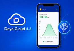
The app allows you to confirm feeds, battery level and history. It is used to monitor the results of the adjustments, not to replace the tests carried out in front of the inverter.
What the screen should tell
A day understandable in seconds
The snapshot should show where the energy is coming from and where it is going. The history must then tell the same story about the day: solar production during the day, battery recharge, house consumption then possible discharge in the evening.
- 01
Production — compare solar power with weather and time.
- 02
Home — switch on a known load and check that consumption increases.
- 03
Battery — the SOC must move in the right direction during charging or discharging.
- 04
Grid — check whether you are importing or injecting, depending on the mode chosen.
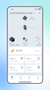
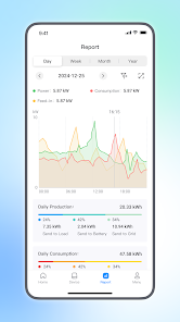
A delay of 5 to 15 minutes may be normal
Additional guideInstall SOLARMAN, connect the Stick Logger and understand the dashboardOpen the complete monitoring guide →The data displayed in the application is not always instantaneous. To check flow direction or security, first look at the Deye local screen; then use SOLARMAN to confirm the trend and keep the history.
Find the cause before modifying
What to check when something is not working?
First notice what you see or hear. Then do the short test indicated without changing several settings at once.
| Symptom or code | Causes to examine | Useful control |
|---|---|---|
| F13 after grid change | The grid setting has just been changed or has not been completely saved. | Check the grid code, save and then follow the procedure to restart the model. |
| F56 / battery too low | The voltage drops sharply when a large appliance starts, or the battery has reached its limit. | Reduce the load and check the cables, tightening and maximum current setting. |
| The Grid arrow is going in the wrong direction | The CT clamp may be mounted upside down, in the wrong location or on the wrong phase. | Isolate the panels and the battery, turn on a known device then take the test shown above. |
| The battery is not working | Time of Use is not checked, the current day is missing, or the Batt value is too high. | Check the line corresponding to the current time and compare Batt with the actual percentage. |
| Fault BMS_Err_Stop | The Deye no longer receives battery information. | Check both sockets of the BMS cable and the selected battery type before disabling the security. |
The Low Batt beep goes off every night
The minimum programmed in Time of Use is probably too close to Low Batt, or a large device is causing the battery to briefly drop. Keep more margin. Muting Beep removes the sound, but does not correct the cause.
The Zero Export lets a few watts through
A small consumption from the grid prevents the Deye from injecting a few watts by mistake. Check the CT clamp first before changing this margin.
The program changes depending on the day
Check the checked days and the time displayed by the Deye. If a day is not selected, the Time of Use ranges are not used on that day.
Should the inverter software be updated?
Updates may fix MPPT or Time of Use. Check out the versions first HMI And Hand In Device Info, as well as the problem encountered. The update can be done via the Wi-Fi dongle, but ask Wattuneed or Deye for the correct version before launching it.
Direct answers
Deye Configuration Frequently Asked Questions
Short answers to the problems that most often bring installers back to menus.
How do I quickly check that my Deye is configured correctly?
Check five points: Time Sync active; charging and discharging current less than or equal to the limit of cables and batteries; Lithium mode with the adapted BMS protocol; CT clamp placed in the correct direction; and sufficient gap between Shutdown and Restart. The System Info screen then allows you to confirm which values are actually active.
What is the difference between Zero Export to Load and Zero Export to CT?
Zero Export to Load only looks at devices connected to the LOAD output. Zero Export to CT uses the clip placed near the meter to see all the consumption of the house.
Why is the battery not discharging even though Time of Use is programmed?
Verify that Time of Use is checked, that the current day is selected, and that the time is within a programmed range. The Batt value should also be lower than the current battery percentage.
What does Batt = 15% mean in a Time of Use range?
This is the minimum we want to keep in the battery during this range. The inverter can therefore use the battery up to 15%, then it goes to the grid. This does not mean that it will only discharge 15% of its capacity.
Why does the inverter cut off while the battery still shows energy?
In voltage mode, a heavy load can cause a momentary drop: for example, under 100 A, the inverter can read 46 V and cut off while the battery still shows 40%. If possible, switch to Lithium mode with BMS, check the connections, consider a larger cable section - for example 25 to 35 mm² if the calculation requires it - and reduce the maximum current before lowering a safety threshold.
Can we use the GEN port for a generator and a Smart Load at the same time?
No. Generator Input, Smart Load Output and Micro Inv Input are three exclusive identities of the same port. A different function requires a specifically designed external architecture.
Should BMS_Err_Stop be activated?
Yes with a lithium battery that communicates correctly with the inverter. If the cable or communication fails, the inverter will shut down instead of continuing without knowing the battery limits.
Why does a Deye SG05 still show Off-grid after the grid returns?
On some SG05 units fitted with the ATS block, the grid may return and the inverter may enter bypass without the neutral-to-earth switching being restored correctly. Wait until startup is complete, press ON/OFF until the display shows OFF, then press it again to restart. First check that the wiring, DIP switches and ATS options match the exact inverter model.
What example Time of Use to use with a Belgian rate 10 p.m.–7 a.m.?
Example to be adapted to the contract: 00 a.m.–07 a.m., SOC 90%, Grid Charge ON, Power 5,000 W; 07:00–22:00, SOC 20%, Grid Charge OFF, Power 5000 W; 10:00–11:59 p.m., SOC 90%, Grid Charge ON, Power 5000 W. Check daily for continuous application, or uncheck Saturday and Sunday if you don't want ALL on weekends.
How long can you expect from a properly adjusted LiFePO4 battery?
As an indication, a battery correctly communicated by BMS, used around 0.5 C, maintained most often between 20 and 90% and between 15 and 25 °C can achieve approximately 6,000 to 8,000 cycles at 80% depth of discharge, or 15 to 20 years at a rate of one cycle per day. Repeated deep discharges, extreme temperatures and currents above 1 C can reduce this duration to around 5 to 7 years.
To remember
A good setting must remain stable when the situation changes
A Deye installation is not successful just because it produces solar. It must also remain consistent when a cloud arrives, when a large device starts, when the grid cuts out and when the battery reaches its limits. The cables and protections first establish what is possible; the menus are then used to respect these limits and to choose how the energy will be used.
Photograph settings, test transitions, and monitor battery life over time. It is this combination that protects the equipment and allows the Deye to become a true energy manager for the home.
Additional documentation and guides
Menus vary depending on series and firmware. Always confirm limits electrical, protocol and grid code in the manual of the installed reference.
Material cited in the guide
See what the main elements look like
These examples serve as visual cues. The reference, power, grid certification and battery compatibility must always be validated for your installation.
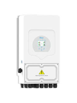
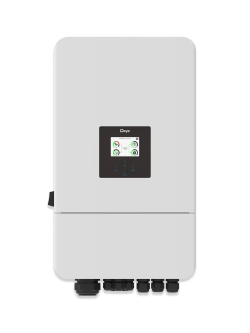
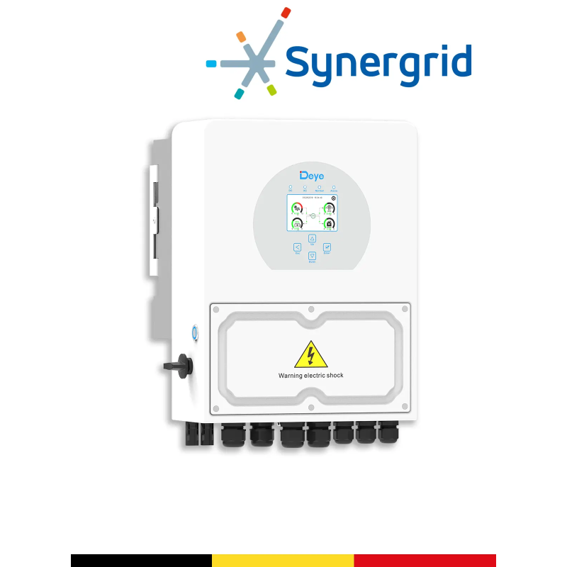 48V Hybrid InverterDeye SUN-5K-SG04LP1-BESingle-phase example approved Synergrid for Belgium. Check availability and power suitable for the project.See the product sheet →
 Communicating LiFePO4 batteryPylontech US5000Example of 48 V module with CAN/RS485 communication, to be connected according to the procedure and limits provided.See the product sheet →
Moving from guide to project
Do you want to check your configuration?
Indicate the Deye model, battery, number of modules, protections and your grid objective. The Wattuneed team will be able to direct the equipment and settings to be checked.